There are described basic principles and algorithms used for colour processing.

As a colour one can consider a perception of a spectral property of reflected or illuminated light by the human eye. Our goal is to detect, to process and to display pictures by a such way, which correctly reproduces colours of the original scene.
The colour si derived from a spectral property of reflected light by an object, while the colour vision is a product of processing of the light by both the human eye and brain. The right colour can't be determined objectively by an instrument, it is fully determined by human perception itself.
The meaning of the colour in objective terms can be specified more precisely: the colour is determined by proper composition of light bands transmitted throughout exactly defined set of filters. The filters approximates colour perception of receptors of human eye defined by CIE 1931 XYZ. By the description, the colour processing is focused to provide the most close approximation of human colour perception.
The astronomical terminology is more vague. "Colour" means a light flux in any filter, not necessary, in a filter appropriate to human receptor sensitivity.
The common method of reproduction of colours is RGB colour model for emitting devices. The RGB colour emitters has distinct spectral sensitivity as human eye, original colours should be transformed to the colour space.
Munipack is designed to handle colours as correctly as possible. There is effort to display of images by colours perfectly reconstructing of the original scene. The authenticity can be limited just only by the used hardware.
Light fluxes acquired by an instrument like an astronomical CCD camera are usually different from ones of display devices. The display devices uses sRGB (PC-type hardware) or Adobe RGB (Apple) opposite to Johnson UBVRI colour system. Therefore, we need transform the colour data each other. Without the transformation, the colours will strongly deformed.
The primary colour space of Munipack is CIE XYZ which is practically colour space of the human eye.
Munipack can display only colour FITSes as is specified. There is no widely accepted colour FITS definition so colour FITSes can be created just only by Munipack utilities. Please, be consentient that the definition can be changed at any time in future.
The colour processing is based on working in colour spaces. Internally, Munipack uses CIE 1931 XYZ and CIE 1976 L*u*v* colour spaces. An input data in another colour space are transformed to CIE 1931 XYZ. The display is in a RGB space.
The colour processing in Munipack starts with loading of colour FITS. The software automatically recognize the type of colour space by reading of CSPACE keyword in FITS header.
When the type is different from XYZ, the data need to be transformed to XYZ. In this case, the first step is prescaling of values. It is the optional step, but usually required for best results. Main goal of prescaling is to give the same flux from a white object in different filters. Unfortunately, the fluxes are violated by a different background and detector sensitivity or exposure time. In light polluted industrial localities, the main source of pollution are sodium lamps. The background for example in blue or red filters is affected differently and we need light of the object not, background. Munipack pre-estimate background levels as the median subtracted by 1-sigma. The fine tuning needs an user experience. The weight of every channel is not pre-estimated by any way. The guide can be for example exposure time, but it may be also derived from the telescope aperture, atmospheric conditions. etc. The prescaling can be omitted (level =0, weight = 1 for all bands).
B'ij = wB (Bij - B0),
V'ij = wV (Vij - V0),
R'ij = wR (Rij - R0).
The colour transformation follows the prescaling. The file ctable.dat is looked-up for the header's identifier. When the colour space is found, the matrix is loaded and all data are transformed. The transformation is usually done by matrix multiplication. When the type remains unknown, the behavior is undefined so colour assignment will random (false colours). Note that the number of input colours can be different from XYZ (tree colours).
X = a11 B + a12 V + a13 R,
Y = a21 B + a22 V + a23 R,
Z = a31 B + a32 V + a33 R.


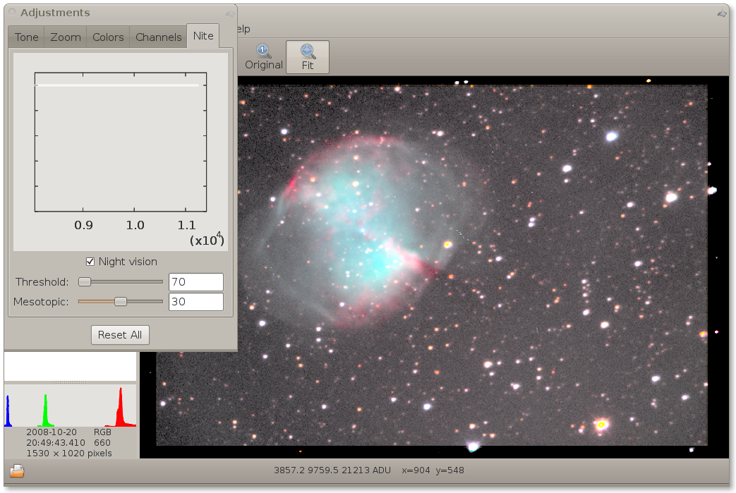
When light intensity decreases, the effective of use of cones is low and the (otherwise saturated) rod cell are activated. The spectral sensitivity of rods is shifted to shot wavelengths with respect to Y trisimulus. The transition region from daily (photopic with cones as receptors) to night vision (scotopic by rods) is mesotopic vision and the break occurs around 0 magnitudes (10-2 - 10-6 cd/m2, see reference) for naked eye.
Munipack simulates the scotopic and mesotopic vision. The scotopic sensitivity is approximated by the formula:
Is = 0.362 Z + 1.182 Y - 0.805 X.
Generally, the photopic, mesotopic and scotopic vision probably operates simultaneously. The detailed mechanism is perhaps unknown so the vision transition are simulated by the (empirical estimation!) logistic function. The logistic function drives many similar effects in real world. Especially, phenomenons of saturated detectors are frequently described by the way.
w = 1/(1 + exp(-x),
x = (Is - It)/wt.
Then output colours are computed as:
X' = w X + (1-w) Is,
Y' = w Y + (1-w) Is,
Z' = w Z + (1-w) Is.
The break must be setup manually and the the both vision are mixed. The parameters Threshold Is and Mesotopic Is are used. The thresholds sets the level corresponds to the zero-magnitude break. The mesotopic sets wide of transition region. This is absolutely empirical value and depends on vision and detector's gain.
The weight determines the types of vision:
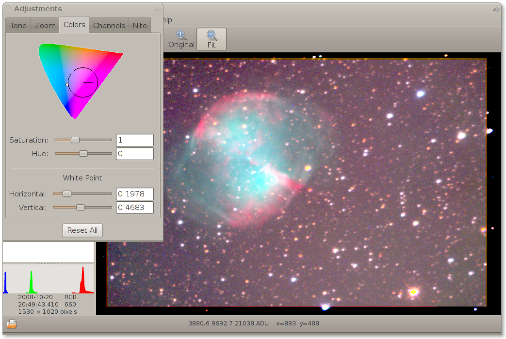
The XYZ colour space corresponds to eye's precipitation of colour light by the cones. The XYZ has no upper limit. The numbers must be zero or positive. Unfortunately, the human perceptions of light intensity and colours is not linear. Therefore to get tunable parameters the parameters are transformed to CIE Luv colour space. The colour space is used to tune parameters saturation, hue and to scale luminosity.
The saturation parameter enable decrease or increase colours.
The saturation is practically multiplier of radius of colour in u,v coordinates.
Hue rotates the pixel in colour space and it is probably useless.
The hue is an angle added to angle of current colour in u,v coordinates.
The white point parameters enable user to fine tuning of white on image. Note that the white is also given by colour temperature. The ideal object for white tuning are cumulus clouds. They are easy available and white is excellent (tested on white etalon).


Finally, the Luv is converted back to XYZ and consequently XYZ to a RGB space. There are two possibilities. The sRGB colour space is widely used on PC-like hardware. If you are running Linux or Windows your monitor, LCD or beamer works in sRGB. The AdobeRGB is very similar (a slightly different parameters are used) and is used on Apple hardware. Note that the AdobeRGB has wider gamut (displays more colours). Your RGB colour space must correspond to your HW, otherwise the output colours will certainly deformed.
The tuning of colour space is available in Preferences. The colour temperature must exactly corresponds to values set on your display.
No other colour spaces are available, but ones might be easy implemented when needs.
The standard image formats stores data in very limited precision of 256 levels on every colour. It is 256*256*256 approximately 17 millions colours. But low-cost CCD chip has dynamic rage more wider and human eye at least over ten orders. The main problem of displaying of astronomical images is correct displaying of the wide range of data on display with 256 levels. The problem is widely known in recent as the high range photography HDR. Moreover, the data has more usage over displaying. For example, the photometric data requires high precision.
Therefore, the best way how to store of data is store raw data with exact definition of photometric instrument (filters, etc.) and use this data by various ways. One from the ways, it can be the colour imaging. The side effect of the way are wide possibilities of image tuning.
There is described algorithm used to rendering of colour FITS images.
The rendering code is implemented in C (fitspng.c), Fortran (colouring/colour.f08) and C++ (xmunipack/fitsimage.cpp).
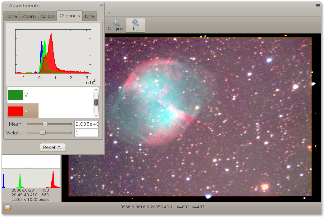
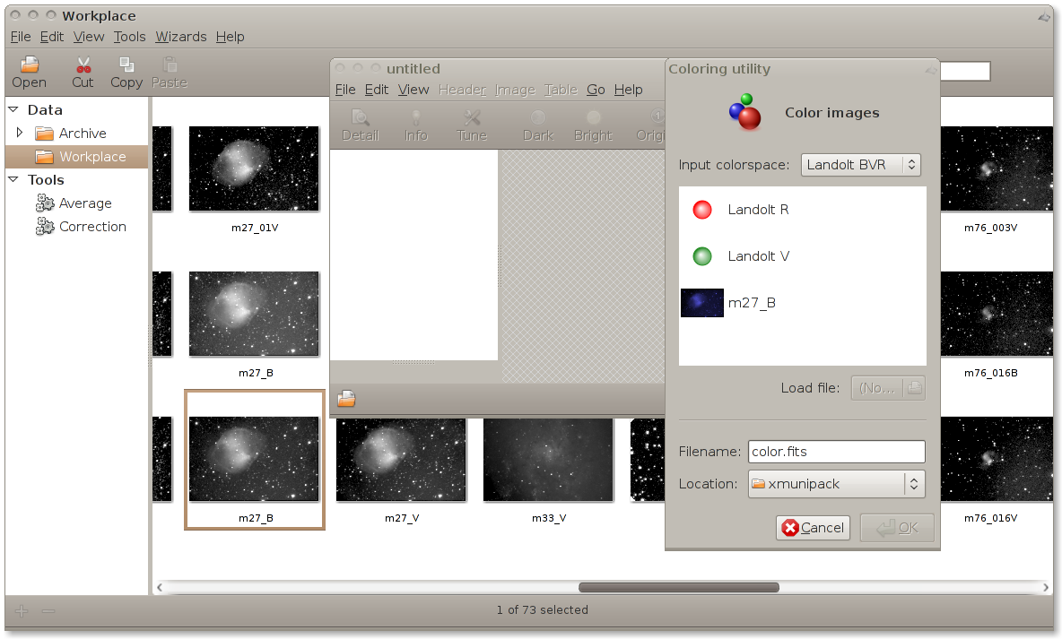
The colouring tool is invoked from the menu of View: File → Create → Colour image
Complete colour management can be driven from a command line. There are two Munipack internal utility colouring providing its. The export from colour FITS to any conventional picture format PNG is provided by fitspng utility.
Composing of images to a colour image is provided by colouring internal utility. It is invoked via munipack command. Use the syntax:
$ munipack colouring -o colour.fits blue.fits green.fits red.fits
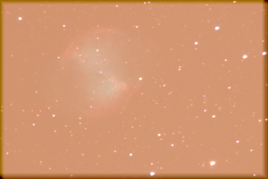
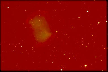
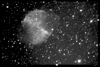
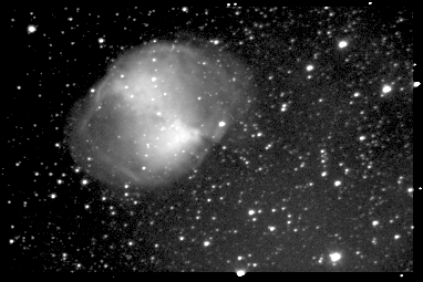
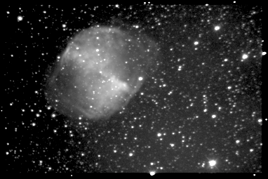
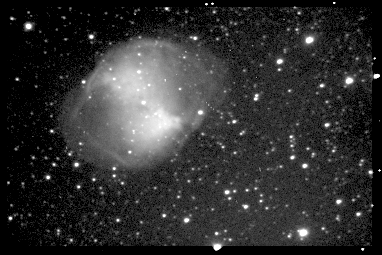
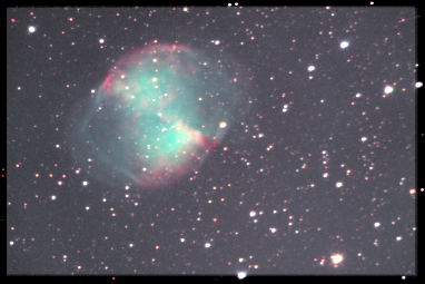
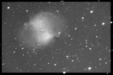
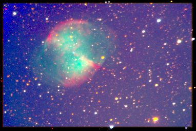
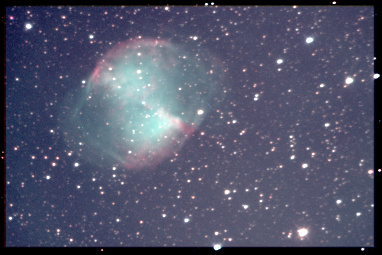
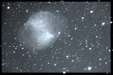
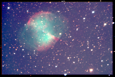
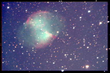
Prepare pictures in a colour space and pass ones in wavelength increase order to create a colour FITS. The test data package contains pictures of Dumbbell nebula in Johnson BVR. The colour image can be created as:
$ munipack colouring -o m27.fits m27_B.fits m27_V.fits m27_R.fits
Images of M27 has been taken by J.Połedniková, O. Urban and M. Kocka on MonteBoo observatory via 0.62 m reflector.